
US

From The Daily Caller
Tim Pearce
Energy Reporter
5:19 PM 08/11/2017
California is receiving $22.8 million from federal disaster officials to aid in cleanup procedures for the February collapse of the Oroville River Dam spillway, the Federal Emergency Management Agency announced Wednesday.
The Oroville River Dam crisis led Lake Oroville to overflow and endangered hundreds of thousands of people.
Both federal and state governments had been warned about the condition of the spillway from as far back as 2005. The crisis caused $500 million in damages. California contends the federal government should pay 75 percent but, depending on the findings of federal investigators, the state may receive significantly less, the Ventura County Star reports.
“That [$22.8 million] was just the first of many reimbursements,” California Department of Water Resources (DWR) spokeswoman Erin Mellon said, according to the Ventura County Star.
Despite what Mellon says, emergency federal funds to the state may be cut off if federal regulators believe the crisis was caused by lack of routine maintenance.
“Is there a maintenance issue here, because they’re not going to cover that. If it’s an emergency response, they’re going to cover,” then-DWR director Bill Croyle told lawmakers in May according to the Ventura County Star.
Three environmental groups filed a petition to Federal Energy Regulatory Commission (FERC) to reinforce the Oroville River Dam spill in 2005. The groups claimed that the dam, completed in 1968, did not meet modern safety standards. FERC rejected the petition on the advice of the California DWS, The Mercury News reports.
During the dam’s last inspection in 2015, regulators inspected the spillway “from some distance,” the regulators’ report said according to the Redding Record Searchlight.
HT/TA
It’ll vanish into the Swamp.
No way on this Earth are folk in the bureaucracy going to be held responsible.
Cross my heart and hope to die.
Auto
Looking for the Donald to bring sanity, but not entirely convinced by the recent seven-eight months.
“””””….. The Oroville River Dam crisis led Lake Oroville to overflow and endangered hundreds of thousands of people. …..”””””
Well I doubt that it endangered the idiots who drove a bunch of heavy trucks out onto that spillway about 12 years ago, and probably broke it back then. They’ll never be held to account for it. The hole appeared right where those trucks were parked. The photos can be found on the web.
Rebar reinforced concrete is NOT pre-stressed concrete. It isn’t intended to be bent with a heavy weight in the middle of a floating section, with no support underneath.
G
PS You can’t “maintain” a spillway that wasn’t designed properly in the first place.
Concrete does not bend; it breaks. Concrete doesn’t stick to steel, so it doesn’t form a real composite structure. Concrete is like ice in sheets; you bend it and it breaks, because it has near zero tensile strength. OK to compress; no good to stretch or bend.
G
Wow george, I guess all those structure that contain rebar are useless in tension of any sort. We should let the designers know that. Same goes for highways, I suppose. That’ll be a terrific cost savings. /sarc
For DJ Hawkins
Most structures I know with rebar – mostly walls – that are unsupported break when you run into them. As for highways, well, last I looked most highways lie on the ground which means they’re pretty well supported. As for bridges, they are build on steel beams, if you’re unsure, take a look at them. As for your comment to George, you owe him an apology.
It was built on the cheap like a sidewalk, concrete on grade with rebar to hold it together. Voids from excavation / subsidence over time created large unsupported areas of it that were never intended to carry a large load without ground underneath supporting it. (The concrete was really only there to prevent to prevent erosion when the spillway was active.)
IMO, for the way it was built, periodic inspections should have been done with ground penetrating radar to find the voids and fill them in.
Mr. Layman here. (When I preface a comment with that it means I know something about the topic but don’t know or understand the details. (Maybe I should preface all my comments that way? 8-))
Pre-stressed concrete involves threads rods running through it with bolts that are turned to “compact” the concrete as it sets. That makes it stronger.
Our newest clearwells were pre-stressed but we still don’t allow trucks to drive on them.
You’re right, if that is what indeed caused the hole, but a spillway of that height needs baffles integrated into the structure to diffuse the water spillage, so as to prevent cavitation. Cavitation will strip away concrete in no time, if the flow is large enough.
It is not possible to know whether this is a design, maintenance or age related failure without having blueprints for the design of the concrete. Sometimes rebar is only used for reinforcement of thermal stresses. Such a design would not carry unexpected loads. Sometimes, voids can form under concrete when improperly maintained. That is usually, but not always, the result of improper maintenance (i.e. sealing) of joints between adjacent slabs. In my experience with concrete structures and concrete pavements, I have not seen enough to be able to guess at the cause of the failure of the Oroville spillway. There are multiple possibilities.
DJ Hawkins ….. apparently you’ve never been in the south …. where the highways indeed are not hint more than crumbled concrete. Guess that rebar didn’t do as good a job as it was supposed to do. ….. and George is right …. I had to redo my patio a year or so ago …. concrete does not stick to rebar or the mesh wire. It just forms a rock around it.
There are many interstate highways that carry thousands of heavy trucks every day that are less than 15 inches thick (the thickness of the spillway slab) but without reinforcing. Driving those trucks on the spillway would have had no effect on the slab even if there were some hollow places under the slab.
Well DJ, you seem to know much more about it than I do. But then I was one of those misfortunate ones that had to learn my ” Strength of Materials ” courses from Timoshenko of Stanford University (well his text book).
The real brainiacs studied strength of materials from the competition text book from UC Berkeley. Since I never ever saw the book, I don’t remember the name of the author but he is every bit as famous as Timoshenko.
Truly elastic materials like most steels, stretch or compress linearly, and are about as strong in tension as they are in compression. If I had to bet, I would say that there are more materials that are stronger (in terms of ultimate yield strength) under compression than there are that are stronger under tension. Ice and concrete are notoriously weaker in tension than they are in compression. For concrete it might be ten times stronger in compression, than it is in tension, but let’s say it is only five times, and lets give it some numbers. perhaps 50,000 PSI under compression and 10,000 psi under tension. (off hand I don’t know the real numbers. for comparison ordinary structural steel is commonly rated at 60,000 psi in tension or compression.
So if I bend a sheet of plain concrete (not reinforced), the convex side will be in tension, and the concave side will be in compression. The sheet will break when the convex side tension gets to 10,000 psi. That’s unfortunate because the concave side is still good for another 40,000 psi, but too bad the slab already broke.
But suppose I put some long bolts through the length of my concrete sheet, like a tube with a rod inside it, and I add some steel end plates, and then I put the nuts on the ends of the rods, and I start compressing the sheet lengthwise, until the concrete is under 20,000 psi compressive stress.
Well hell, I still have another 30,000 psi of compression I could go, but now I also can go backwards with 30,000 psi externally until I cancel out my 20,000 pre-stress, and then use up my piss poor 10,000 psi of tension.
So now I have a nice ” PRE-STRESSED ” concrete beam, that can withstand 30,000 psi of additional tensile of compressive stress.
And that concrete beam will bounce like a diving board, and if you hit it with a sledge hammer, it will ring like a gong.
Pre-stressed concrete is one of the miracles of structural engineering.
But rebar reinforced concrete is NOT pre-stressed concrete and it needs to be supported.
The Oroville dam is built out of gold mine tailings. Totally junk crap, that washes away with every little rain storm, and there was virtually nothing of any consequence supporting that spillway, and what was underneath was on a very steep pitch; NOT level ground.
Roadways have the entire weight of the earth pushing on one side of them, so they aren’t about to go anywhere. Ergo, rebar suffices to provide some protection against local cracking, and eventual failure.
Modern composites made from materials like glass or carbon fiber typically use fibers that are stronger in tension than in compression; but usually more like a 10% differential, rather than a factor of five or ten.
For carbon fibers, the types with the higher modulus of elasticity, usually are much less strong in compression, than in tension. The more modest modulus materials are more symmetrical.
Boron fibers, in addition to being immensely strong, are highly unusual in that they are stronger in compression than they are in tension. About 1.1 million psi in compression, and about 900,000 psi in tension. (I’m just remembering these numbers so I may have moved a decimal point.
I know when I designed my bridge over my moat, I used 60,000 psi for the structural steel number so I designed for a maximum loaded stress of 16,000 psi on the bridge with a H20 truck on it. Well actually it would carry an A1M1 Abrams main battle tank with a second one stacked on top.
The Oroville spillway is very wide for the thickness of the concrete floor, and how they get away without using pre-stressed concrete is beyond me.
And those trucks WERE parked right where that hole eventually occurred. It would take more than a few beers to convince me, that they didn’t break the damn thing back then in 2005 or whenever it was they were “inspecting” it.
G
PS When ordinary homogeneous materials fail under compression, the failure is usually a shear at 45 degrees to the applied stress. The material doesn’t just turn into whiffle dust and collapse into a powder, it splits sideways, so the failure is usually quite sudden and explosive. It tension, it starts to narrow laterally until it just pulls apart like toffee.
G
“””””….. additional tensile of compressive stress. …..”””””
” of ” = OR please Chasmod.
Thanx G
I’m responding to a comment that was directed to George.
For the engineering types here do a quick back of the envelope calculation of the effect of the water flow over the “ski jump”. Looks like it basically landed where the initial break in the spillway occurred.
There were some assumptions that I had to make but much could be derived from various comments and link to construction documents on the ‘metabunk’ website.
That was a close call had another pinapple express or two come along. The dam was ok but possibility of the emergency spillway at 60 foot vertical breach could have been bad.
G. Smith: Look up the term “deformed steel bar” which is how structural engineers have transferred stresses from concrete to steel for the last hundred years or so. Considering the large numbers of concrete bridges, buildings, elevated slabs, etc., something must be working.
Thanks for the tip Chris; I’m always eager to learn something new, so I’ll look it up.
So it seems strange that this 100 year old technology didn’t seem to work very well in this one case. The steel clearly did a lousy job of supporting the concrete.
Now if they added about 3% of sticky rice to the cement, like they did in the great wall of China, then the Oroville Dam spillway might be able to last for a thousand years also.
G
It appears I missed the condition from your prior post that the slab section was unsupported. In that case, I agree, failure was likely without pre-tensioning. I withdraw my /sarc.
It is hardest for The Donald (The President) to reign in the lunacy of congress when both houses are 1/2 crazy to begin with
Sometimes I think 1/2 of them are 1/2 crazy and the other 1/2 are 2/3 crazy. (Like a fox.)
Presidents aren’t supposed to reign!
* “rein in”
“Looking for the Donald to bring sanity”
Put not your trust in princes, in mortal men who cannot save you.
They will die and be buried, and their plans will be buried with them.
Ps 146:3
“Cyrus, God’s Instrument”: Thus says the Lord to his anointed, to Cyrus, whose right hand I have grasped… Isaiah 45:1.
Well, I just came back to this thread and it is obvious that George just ended BJ Hawkins career on WUWT but I was a refresh or so from reading George’s response.
Good job George.
If you’re going to pronounce someone’s demise, you might at least get their name correct, naysonu.
Juan Brown of the Blancolirio youtube channel has regular updates about the repairs to the dam.
Not the most succinct source since his data is in many separate videos, but he has done a fine job getting the facts and reporting them.
I’ve been watching them all, from the start.
What an excellent resource he is!
Him and the Mighty Luscombe…
That an individual can provide such extensive, level-headed, and interesting reportage… the manifold failings of our huge media complex become so obvious by comparison.
As a long-retired civil/structural engineer who spent some time working along side the Corps of Engineers on a few large scale water resource projects, I am fascinated by the quantity and quality of his work. Juan’s August 7 report alone touches on so many details of so many facets of the job and yet is not at all overwhelming.
I tip my hat to Juan Brown.
so they pissed their money away…and the rest of us bail them out
It’s closing time…you don’t have to go home….you just can’t stay here
Given their record, any money to California is money down a rat hole.
I would say it is gone long before it gets anywhere near and rats and/or holes.
Do I suspect a pattern here? It seems the same thing happened to the money shoveled to New Orleans for pump repair or something.
It’s a quote, so maybe there’s not a typo if Bill Croyle wrote it. (I usually don’t spot my own typos till after I hit “reply”.) But if it is a transcript of what he said, perhaps it should be punctuated:
““Is there a maintenance issue here? Because they’re not going to cover that. If it’s an emergency response, they’re going to cover,””
Hi Big G
In the little country of Monte Negro (pop. 650k, then part of Yu) about 7-8 years after Oroville , in 1976 Piva hydroelectric station started producing electricity (360MW, annual output 800GWh) .
Dam is 220 m high (against Oroville’s 235m) had no problems up to date.
Maybe you over there in California need a bit of help from the Balkan’s middle of nowhere construction engineers. /sarc
http://www.elektroenergetika.info/heteslike/piva-epcg.jpg
addressed to: george e. smith August 14, 2017 at 2:19 pm
Thanks Vuk. Can you point to where the water is pulling on that curved pile of concrete there ? !
Oroville Dam is just a pile of mine tailings
g
Hi Big G
Not entirely sure what you mean
This short video has aerial views of the dam
https://youtu.be/BAPw6nbHfUA
Maybe Vuc, I happened to catch you between the Schnapps, and the naps.
I was alluding to the pronounced upstream convex curvature of that tall dam to emphasize just how that turns the whole dam thing into the wildest pre-stressed lump of concrete in those parts.
Don’t need any steel bolts to pre-stress that baby.
The water “pulling” on the dam is probably just some local taking a pee over the dam.
G
Maybe you over there in California need a bit of help from the Balkan’s middle of nowhere construction engineers.
Care to post a photo of the superbly engineered spillway?
High Phil
Lot of photos on the web,
https://www.google.co.uk/search?q=Piva+hidroelektrana&client=opera&hs=ahh&source=lnms&tbm=isch&sa=X&ved=0ahUKEwi2-dTc2dnVAhWELMAKHTiaBZAQ_AUICygC&biw=1138&bih=806
or google ‘Piva hidroelektrana’ and select ‘Images’
vukcevic August 15, 2017 at 9:55 am
High Phil
Lot of photos on the web,
Not of a spillway!
Is this what you are looking for ?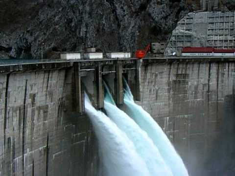
https://www.cdm.me/ekonomija/he-piva-proizvela-301-gwh-struje/
vukcevic August 15, 2017 at 11:21 am
Is this what you are looking for ?
No, there is no spillway at that dam.
Thanks for the observation Phil.
If it doesn’t have one, it obviously didn’t need one, since only recently celebrated 40 years of successful and trouble free operation. It is to the credit of the construction engineers for not providing spillway and not wasting money of this small relatively poor country.
Hi Phil, hope you are still about
I had to find out what is meant by ‘spillway’ (ispust) for a hydroelectric or any other dam.
Fact that I was wrong, taking your word for it, it’s no surprise, but you appear to be knowledgeable about the subject and still wrong.
Dam has three spillways: one at the top, one in the middle and one at the bottom at the water line, just visible (see the short video above at 50sec, etc)
vukcevic August 16, 2017 at 6:31 am
Thanks for the observation Phil.
If it doesn’t have one, it obviously didn’t need one, since only recently celebrated 40 years of successful and trouble free operation.
Yes it doesn’t need one, it’s a completely different configuration and construction, being in a very narrow steep sided valley. It’s concrete construction unlike Oroville and therefore can have an overflow over the dam itself (rather like Mt Shasta). Also it appears to be only a hydroelectric dam, whereas Oroville is hydroelectric, water storage and supply, and flood control which along with the geography necessitate the spillway.
I note numerous wet spots on the face of the dam and near the abutments that should be of some concern.
Orville is an earthen dam not a curved concrete one like Hoover.
With regards it being a maintenance issue or an emergency issue – last I read the dam had an issue with the hydroelectric facility in that they couldn’t open the gates because an idiot had run a test that damaged it, thus you can’t call it an emergency issue. Looks like Brown had better find some more pixie dust to cover their butts if they want this to fly.
Tom O August 14, 2017 at 2:51 pm
With regards it being a maintenance issue or an emergency issue – last I read the dam had an issue with the hydroelectric facility in that they couldn’t open the gates because an idiot had run a test that damaged it, thus you can’t call it an emergency issue.
That was not the hydroelectric facility it was a river valve system, the initial purpose for which was to divert flow during the construction of the dam. Subsequently this had potential as an emergency release valve, in 2009 its use for such purposes was tested as part of a study to determine whether it could be used safely. Unfortunately they found that when used at 85% of capacity it self destructed, if they hadn’t done that test and tried to use it in the recent event it would have self destructed then! In any case my understanding is that the valve has a capacity of 4,000 cfs compared with the 14,000 cfs from the fully operating hydroelectric plant and the peak inflow of 190,000 cfs during the emergency. Its basic function is to maintain minimum cold water flow for the Feather river at times when the water level in the reservoir is below the intake level of the spillway.
The new system was tested successfully in 2014 however its use during the recent emergency didn’t change anything.
The back up from the flow over the spillway raised the level in the outlet pool to the Hyatt power plant above the safe level and the power plant had to be shut down to avoid flooding. Once the pool could be cleared of debris and the water level lowered, generation could be resumed allowing up to 14,000 cfs flow by that route (that’s the flow responsible for the current lowering of the water level).
After the spillway was damaged a lot of debris generated by the failure clogged the river and forced the shutdown of the power house. water exhaust from the power house became clogged and they had to shit it down. Also due to all the work going on at one time they had to cut the power lines to the power house. Without any way to ship electrical power out the water flow to the power househad to be shut down If the water flow had been left on the voltage on the disconnected turbines would continue to increase util the generators would burn up.
“If the water flow had been left on the voltage on the disconnected turbines would continue to increase util the generators would burn up.”
Nope. No current flowing = no heat. Over speed of the turbines overheating their bearings perhaps?
Bullcrap! Let Jerry pay for it with reallocated bullet train money.
Can’t do that! He has to distribute those funds to all the crapitalists friends in CA. (sarc)
Why are you using a sarc tag?
+++++100
I thought the wanted nothing to do with the US… now here they are standing there with their hand out.
Hypocrites, all of em.
Good point. If California left the Union, however, they would still get the money. It would just be called ‘foreign add’. Either way…it still ends up mostly as graft.
If California wants nothing to do with the USA, they should begin returning those Tesla credits and welfare checks. I understand half of all Tesla’s were purchased there and of all welfare checks written, California gets a full one third of them. I see a pattern. Jerry Brown, can the citizens of these United States have their tax money back?
Lurking,
Yes, just more proof of their rank hypocrisy.
It is a fairly safe assumption that the dam’s problems can be blamed on global warming, at least by those in the professional global warming game. (Truth and facts are not the issue here.)
The bigger issue is that when everything is 100% blameable on global warming, everything then becomes something that should have been anticipated. At what point does California get told that they can’t have their cake and eat it in the global warming blame game?
Second graph from the bottom should be California DWR, not DWS.
According to one of our govt green television stations California is in the grip of a terrible drought and the dams are nearly empty , no use fixing the dam if it’s not going to fill again .
George is right of course, us Kiwis know about Hydro. Having no other States to steal lecky or water off. grin.
More seriously, swamp drainage appears to have no effect for all your work, like cutting a tree. Until the job has progressed enough for the outflow, or falling, to start. Which it does with acceleration. And many cries, quickly growing faint in this sort of situation………
A recognized technical journal has revealed that the spillway lacked steel reinforcement which would have held the concrete together. Incredible revelation. Video of the concrete exploding out of the spillway verifies this revaluation.
Metabunk covered that charge months ago . There was rebar . It just did not show up in the videos because of the distance they were shot at .
There were photos on other sites that showed rebar.
Also, IIRR, the trucks were on the spillway to investigate extant cracks.
One of the photos I have seen clearly showed the rebar; but from the picture it looked more like chicken wire than substantial composite re-enforcement. What I couldn’t believe was how thing the floor look for such a wide unsupported span of concrete.
Since it’s an “earthen” dam, it is really just a monster pile of dirt, and as I said it is mostly old mine tailings material; that after all is pretty much California “Gold” Country.
Now I don’t have any reservations about the dam itself, but the emergency spillway could have used some deep driven concrete pilings to prop the bottom up even with the dam material washed away. And the problem was, that once a hole got punched in there, with all that water going over it, well it just hastened the washout of what support material had originally been there.
G
A design review in 1974 indicated that there was rebar, though with proper base support the rebar would have been irrelevant to the structural design of the slab. It would be there to control random cracking from thermal stresses not to provide structural strength.
Yeah, it was built like a sidewalk not an interstate overpass.
I’ve been following this mess closely since it happened. It’s pretty clear that the failure of the spillway is a result of the spillway not being built according to the original plan, which called for it to be constructed on competent bedrock. In actuality, much of it was built on graded fill. Not only that, but there is insufficient thickness, insufficient rebar, insufficient sealing at the expansion joints and insufficient drainage. The spillway has been a 50 year slow-motion train-wreck. It would be easy to blame this on the contractor, but DWR had the spillway opened up many times over the years and they no doubt knew these issue were present, but they turned a blind eye and the failure resulted. In addition to the spillway, the gate structure at the top of the spillway has been in a similar slow-motion process of failing and DWR has been doing virtually nothing about it. Bureaucrats like those within DWR are a cancer.
The upper, flatter portion was constructed on native rock. The lower part was built on an apparently uneven fill. With 20 feet of water in the spillway (it likely never got that deep) and a 15 inch slab the vertical load would have been only 1,400 lbs per square foot, which does not take much of a compacted base to support.
Sealing of the joints was a non-factor. In water carrying structures subject to flotation one method to prevent flotation is to have controlled leaking of the groundwater into the structure when the structure is empty and subject to flotation. So the leaky joints would have reduced the real problem, which was flotation (buoyancy).
The drainage system was either inadequate or became plugged. This allowed water underneath to push the slab up with the very wet ground conditions at the time of failure. The water under the slab has to produce an upward pressure of only 3 feet of water to lift a 15 inch slab.
If you look at the photos of the spillway site with the spillway removed, you can see how deep and wide the areas of incompetent rock are. They are massive. It will take hundreds of thousands of cubic feet of RCC to fill them.
The lack of joint sealing enabled large volumes of water to flow into / underneath the spillway through the joints. This flushed the fill out from underneath the spillway resulting in huge voids. There are photos of the spillway with the gates open where you can see the large volumes of water emerging from the drains back into the spillway. Even photos from years ago showed this happening. In some cases, the drainage is dirty, indicating the presence of fill in the water. There is no other explanation for the large volumes of water from the drains than leakage through the joints.
There are also photos with the gates closed that clearly show water that leaked through the gate seals flowing down the spillway and disappearing into the joints.
The joint leakage might not have been such a problem if the spillway was built upon competent rock and properly anchored. The spillway was supposed to have been built upon and anchored to competent rock to prevent an outcome like the one which occurred. It wasn’t. The resulting failure is as close to definitive proof as you expect.
Add the volume of water at high velocity flowing OVER the top of the spillway, you will then have lowered the upper pressure, causing lift, which would induce more water flow from below, and rinse, repeat..
Both federal and state governments had been warned about the condition of the spillway from as far back as 2005.
Not correct, different spillway.
Oroville Dam was in the final conception at 450 ft. Flood control, local irrigation valley water shed during summer. Northern California could not afford to build the 450 ft dam. Politics found the solution, add 300 ft for Southern California (So CAL) water needs. Everyone happy until the bacon burned-debt much larger than told. Pumping water to So Cal was also more expensive than advertised.
First question that has never been properly explained – Why did DWR fill the reservoir in January? Flood control apparently became secondary for water to So Cal. State scientists/meteorologists claimed drought-drought. Flood control was swept under the rug by actions.
FERC re-licencing 2007 identified Emergency Spillway issues, Primary Spillway issues, etc. 2013 Spillway inspection contractor wanted to bore inspection holes in the identified spillway cracks. State said no. Contractor suspected erosion creating cavities in the contract site. Side discharge ports (near the top of the wall (called trainer) in the area of the inspection contract were not all working.
There have been many other issues identified prior to the spillway failure. None were addressed for maintenance properly.
There are pictures on the DWR site as well as private pictures showing heavy rebar – 2 inch in places and lots of smaller pulled straight out (water direction) and broken off in some cases. Maybe not enough rebar, but failure of the concrete-rebar in the original inspection site doomed the entire spillway via underneath erosion. .
Math may not be slide rule accurate but – 100,000 cubic feet per sec spillway flow (considered the high point even though the capability is near 140,000 cu ft/sec) weighing and moving at the same time 6 million pounds per sec. When the dam was in its newness, citizens could drive across the spillway discharge gate (bridge) and some people even walked that area – the vibration was very noticeable, one could almost feel that 6 million pounds romping down the spillway. For several (?) decades when the spillway is above a minimum operation point all traffic is closed across the spillway.
Normally the dams in California are allowed to fill all winter long until the lake reaches flood control depth. At that point they then adjust the flow of water through the turbines to maintain the flood control depth. At the end of the rain year snow melt is allowed to fill the reservoir to capacity. In most years the lake doesn’t reach capacity. At the end of summer last year the lake was well below normal levels and nearly empty.
However last winter the rains started earlier than normal and they were heavier than normal. By December the lake was close to flood control level. Then the rain really got going and they couldn’t dump enough water through the turbines to prevent the lake from filling to capacity. But the designers had designed the dam with that in mind and included the spillway. With that spillway open there is no way for rain or snow melt to fill the reservoir. When the lake got the the spillway level they opened it and it failed.
Even through they turned off the water right way the damage was already to extensive to repair. And they were concerned that using it further could wash the entire spillway way. So they elected to allow the lake to fill to the emergency spillway level. An the earlier predictions that the emergency spillway would not hold up turned out to be correct. That forces them to use the spillway regardless of the risk. Fortunately the undamaged portion held up until the rain stopped about a month and a half later.
The dam was not operated differently due to the drought. It was operated the same way it was when it cam on line 60 years ago. They had no intention of filing it in January. Normally they wait until April or may to fill it beyond the flood control level. But when you get at least 200% of normal rainfall in 3 months there isn’t a lot you can do.
Why so much for a bit of readymix, rebar and rock anchors??
“Why so much for a bit of readymix, rebar and rock anchors??” Most of the cost is planning, labor and machinery to put it where it has to go.
$22.8M? Is that all? seriously, the site is gigantic, as shown in the excellent reports by Juan Browne, latest of which is here:
https://www.youtube.com/attribution_link?a=JxIS0AYRU1dtW5aZ&u=/watch?v%3Df9fxVkWv-58%26feature%3Dem-subs_digest-vrecs&g=AF35woQi7oCS1WqDIvni4A59mfIMjTG9p71YQDB0CAZlvOsMK6niZNuuaW8keZ1cxQc8lfrdSrQbFJvk3GT36tfj8q8kQpiz7sy7LAGwoewhQDKGfS9-28ScgbxMTpNhL1ddKOkgyYFELSyJR5_Ofh6j849WIbiZLIJgQvwW6tlN2rNwZCV2Ml8xotlA6J4wpfxL0Lu5-ri1nW4
The article says $500M in damages. This is just what they’ve gotten from the Feds so far. I think that’s just the FEMA effort. The Fed isn’t on the hook for the $500M.
Funny… at the time of the disaster they were saying only $200M. My, how costs grow when Kalifornia state government gets involved.
During the dam construction, local newspaper owner Dan Beebe railed against claimed workmanship, inferior concrete, outlandish cost to temporary visitor viewing place that would eventually be covered by the dam itself. One would need to research the newspaper archives to review these editorials.
Should have inspected it from close up.
Um ! I think there were four trucks sitting on there in 2005, and they don’t allow fishing on that spillway, so I would guess they were inspecting the spillway from about as close to the spillway as you can get.
G
I have that picture. Under the impression that it was 2012 or 2013 an Engineering Contractor wanted to bore inspection holes where the pick ups were parked. State refused to allow. Had one hole been bored, the undermining at that specific site (parked pickups) is also where there were visually noticed cracks in the spillway concrete. This Contractor offered repair the specific site including grout pumping in the void (estimated as no bore holes allowed), repair the migratory water damage underneath the slab, remove vegetation along the border of the spillway (FERC 2007) costing $5 million. State declined. Had the bore holes been allowed, that section and perhaps other places down slope from the ‘cracked area’ may have required complete replacement so the $5 million would have been mute point. The fix, related in conversation by an Oroville local – working for the ‘fix’ contractor said they used some high-tech black goop injected into the cracks and concrete pour seams(not supposed to open up). After the initial site failure, water shut off and an inspection showed some vegetation impingement on the spillway perimeter – roots. This spillway similar to an engineered replacement Folsom (near Sacrament) dam spillway in the past 4-5 years. Pictures of the new Folsom look very similar to the original Oroville Dam spillway construction pictures. These spillways are load bearing – Oroville at 100,000 cu ft/sec is about 6 million pounds per sec, moving down slope.
Quote
Both federal and state governments had been warned about the condition of the spillway from as far back as 2005. The crisis caused $500 million in damages.
Unquote
As I said why so much????? Its a spillway not a load bearing structure.
No a public group warned that the emergency spillway would not hold up if it was ever used. The US and state government disagreed and nothing was done. Besides it was never intended to be used except in an emergency. But the spillway the that failed was not the emergency spillway. It was the regular spillway of which there were no concerns by the public, state, or federal officials.
Whe the regular spillway failed and the lake filling faster then expected they had to use the emergency spillway. And well the predictions about the emergency spillway were accurate. Note many other dames throughout the US have emergency spillways like lake Oorville. All of those will also have to be looked at.
The emergency spillway did what emergency spillways do, which is to erode. The concerns expressed in 2005 were from the standpoint of soil eroding into the Feather River plugging and polluting it. They were not on the basis of the safety or structural integrity.
Emergency, emergency. Get the job done, now. The Emergency Spillway in use but a short time gouged very large holes – trenches close to the spillway base. The discharge apron of that spillway had not been hard faced and concern that undermining would cause catastrophic failure. Large rock (like 2 rocks on one low-boy transport, came from far places – Redding CA, very large excavators as far away as East Nevada. Emergency funding in the state was labeled 009 coding and in this case used as a temporary band-aid. Some of the emergency expenditure-repair needed further modification and or replacement later on. Large rocks – rip-rap were hauled into the site from nearby as well as far reaches 24-7 about 2 weeks.
California is one giant rest stop/picnic area for the DNC…let them pay for it.
Pretty clear it was “all of the above”, including a significant maintenance component. Dont think Sacramento can hide from this one. So we have NY subway system, Oroville and other dams, critical infrastructure being ignored. But we can spend billions on climate change and trains to nowhere…. see:
https://ww2.kqed.org/news/2017/07/21/oroville-dam-spillway-report-alleges-dwr-ferc-negligence/
Following is a link to a very interesting report cited in the story linked by Don Gleason above.
http://www.documentcloud.org/documents/3898834-Bea-and-Johnson-ROOT-CAUSES-REPORT.html
It goes into the potential causes of the failure,though it spends far too much time advocating systems of analysis rather than the spillway itself.
From the FERC relicensing DWR’s own words LESSONS LEARNED -The main lessons learned through the Oroville Facilities relicensing process are the importance of open, honest communication and good faith efforts, as well as establishment of a clear process for stakeholder involvement. The following guidelines can be useful for licensees in complex relicensing efforts. (http://www.hydroworld.com/articles/hr/print/volume-27/issue-3/feature-articles/ferc-licensing/a-retrospective-on-the-oroville-facilities-relicensing-making-collaboration-work.html)
Just to fire up a few flames. The spillway was a load bearing structure. Imagine 60,000 to 100,000 cfs H2O at 64+ lb/f\cu ft going over a ski jump and landing on a specific point of the spillway.
Anyway, what was the design of the entire spillway system? Was the design stated to begin releasing above ~800 ft which would have averted 100,000 cfs releases? Did someone/bureaucracy decide to add a 100 ft or so because of a possibility of global warming/drought possibility. Crap shoot at the least! Let the betters pay!
The upper spillway was at a slope of 1 or 2 percent and transitioned over a couple hundred feet to the lower spillway which was steeper at a slope of about 5 per cent. This transition is much flatter than necessary for the water to remain flowing on the concrete of the spillway. Compare to the change in slope of an Ogee spillway which is shaped to just fill the space under flowing water as it flows over a crest. The transition of the Ogee is much quicker.
There was no “ski jump” for the water at the transition. The transition was far too gentle.
eyesonu August 15, 2017 at 4:15 pm
Just to fire up a few flames. The spillway was a load bearing structure. Imagine 60,000 to 100,000 cfs H2O at 64+ lb/f\cu ft going over a ski jump and landing on a specific point of the spillway.
Good job the engineers were smart enough to design it so that doesn’t happen.
Anyway, what was the design of the entire spillway system? Was the design stated to begin releasing above ~800 ft which would have averted 100,000 cfs releases? Did someone/bureaucracy decide to add a 100 ft or so because of a possibility of global warming/drought possibility. Crap shoot at the least! Let the betters pay!
Well on 1st Jan the level was 781ft with inflow of 4500 cfs with 0.12″ of rain.
Over a few days in early Jan they had 6″ of rain and inflow increased to about 90,000 cfs (daily avg) and the level rose to 844 ft. Once it got over ~850 ft they were able to use the spillway and the level was stabilized with about 20,000 cfs outflow. Another couple of inches of rain got it up to 855′ but outflow brought it down to 850′ by the beginning of Feb. Another 6″ of rain in the next week raised inflow to over 150,000 cfs which is when the problem with the spillway occurred. Your conspiracy theory has no basis.
Show your work.
Below is a link of the oroville spillway in use before the damage.

When you look at the picture the water doesn’t jump off the upper spillway and then land hard on the lower spillway. The water doesn’t separate from the spillway at all under normal operation as the designers. originally intended.
for some reason the link disappeared:
Show your work. 70,000 cfs at 900 ft pond elev. If it is too much for you go to school.
Look at the links Steven F has provided. The photos show no ski jump effect.
Look up an Ogee crest weir, as I previously suggested. The initial fall is far steeper than the transition or the lower part of the spillway.
Look also at the methods used to estimate the flow from a fire hydrant, from before we had reliable flow meters. They measure the distance and fall from the hydrant.
You have the radical idea that no one else is advocating. It is up to you to show your work.
Sometimes I don’t follow the herd.
Designing the spillway profile to follow a ballistic trajectory for the water, sounds like an elegant refinement, I would never think of. Well that’s why nobody would pay me to design a dam or a bridge for them. Well I designed my own moat bridge, and a State licensed Civil Engineer told me it would work fine. But then the water folks wanted me to spend the insurance money (since they broke the original), just to survey the site for the new bridge. So in the end, I just repaired the hundred year old bridge, even though my insurance company gave me enough funds to build the brand new bridge the Civil engineer had reviewed, so I now have just a repaired 100 year old bridge. So the water folks were the big losers.
I guess real ski jumps follow some sort of ballistic curve, so it seems like the skiers are hundreds of feet in the air, instead of just skimming the snow.
G
I will. And as a taxpayer (if you are), you should too. It is the death of a thousand cuts (or more). Billions and billions are wasted this way just at the Federal level. If you add in all the state and local governments it is a staggering amount. I know for a fact that I pay well over 50% of my income in Federal, State, and Local taxes and fees. It is infuriating to think that so much of it is wasted by incompetent/corrupt government officials. Frankly, if you are not outraged, then you are part of the problem.
Best media coverage of the Oroville Dam is by this vblogger:
https://www.youtube.com/user/blancolirio
Over the last six months, Juan Browne has created 56 (and counting!) fascinating videos about the Oroville Dam situation, averaging 12.2 minutes each. If you want to understand the topicin depth, be prepared to burn 11.4 hours to watch it all at normal speed, or 7.6 hours at 1.5x speed.
Phil. (August 16, 2017 at 5:41 am )
I’ve been busy this week but decided to check back to this thread. Thanks for your input. You seem to be informed of the flows , pool elev, etc. I looked into it as it was happening and pretty much moved on since.
If you are an engineering type with basic hydraulics understanding and an understanding of a ballistic curve (basic physics of horizontal velocity vs acceleration of gravity) it is relatively simple to plot a back of the envelope curve. Locate the profile of the discharge chute (spillway) and bring your ballistic curve of the water onto the chute below the ‘ski jump’. If I find time I’ll look over my always cluttered desk and maybe I can find the notes I used in my earlier calculations and show my work. But to be honest my tractor repairs are much more important to me now.
There are two ways to get 90,000 cfs through the chute. Lower velocity and deeper depth OR higher velocity and less depth. If the operator allows the pond level to rise 50 ft before release then the discharge will be under higher pressure and therefore the velocity will be much greater for a given flow rate. The ballistic curve will change at the ‘ski jump’.
If the original design was done to allow for releases to begin to maintain pool elev at I believe was about 814′ (bottom of spillway ?) and the operator brought the pool elev up another 50 ft or more to bank/conserve water then that could have led to a flow velocity exceeding the design criteria of the spilllway. Over 6 million lbs. of water per sec. accelerated by gravity and ….. well the result is obvious.
eyesonu August 18, 2017 at 7:02 am
If the original design was done to allow for releases to begin to maintain pool elev at I believe was about 814′ (bottom of spillway ?) and the operator brought the pool elev up another 50 ft or more to bank/conserve water then that could have led to a flow velocity exceeding the design criteria of the spilllway.
The floor of the spillway is at 814′ so until that is reached there can be no flow over the spillway. The practice is to maintain a certain head because if the flow into the valve is too shallow it can scour the inlet and cause damage. My understanding is that the optimum is about 850, it reached 820′ on 1/09 at which time the inflow was ~90,000 cfs, they gradually increased the outflow over the next couple of days (flood control rules limit how fast they can change the flow rate) and on 1/14 they had balance at about 849′ (23,000 in, 21,000 out). They balanced it between 849 and 854 until the 6th Feb, on the 5th the inflow was ~31,000 and outflow 30,000 cfs. The problem started the next day when the inflow went up to 49,000 they increased the output and still kept it about 850′ but then the break happened. Several more inches of rain increased the daily average inflow to 155,000 cfs, Water level went from 850 to 902 in a few days.
If the outflow is unrestricted at 852′ the outflow is 100,000 cfs.
On the 7th the hourly inflow rate went up from 77,000 to 132,000 in 6 hr, while the outflow was at 47,000 and then increased to 57,000 cfs the water level only went up a couple of feet to 854′, but that’s when the spillway broke. Inflow peaked at an hourly rate of ~190,000 cfs which rapidly pushed the water level over 900′.
The design criterion of the spillway wasn’t reached at anytime
HTH
Phil, I appreciate your dialog. As you carefully state “your understanding”, I’ll be rather blunt that your sources or “understanding” has more holes than a fishing seine.
To state that at low flow starting at 814′ would cause scouring is complete BS. An optimum flow at 850′? Optimum for what? Equal BS.
Please check your sources for your “understanding”.
I’ve simply offered insight here and not going to get into an absolute bullshit discussion with you.
You win! I will not play with you! Maybe someone else will.
Phil;, I cross checked your values as in the above comment of yours. What kind of BS are you pushing here?
http://cdec.water.ca.gov/cgi-progs/queryDaily?ORO&d=17-Feb-2017+08:15&span=30days
One more for you pertaining to your comment.
http://cdec.water.ca.gov/cgi-progs/queryDaily?ORO&d=18-Jan-2017+08:15&span=30days
eyesonu August 18, 2017 at 8:24 pm
Phil;, I cross checked your values as in the above comment of yours. What kind of BS are you pushing here?
http://cdec.water.ca.gov/cgi-progs/queryDaily?ORO&d=17-Feb-2017+08:15&span=30days
That’s the source of the daily averaged data and it confirms the values I used, e.g. I said:
“Several more inches of rain increased the daily average inflow to 155,000 cfs, Water level went from 850 to 902 in a few days.”
The site you referenced gives the inflow as 155498 cfs on 2/09.
I also referred to hourly data which can be found here:
https://cdec.water.ca.gov/cgi-progs/queryF?s=ORO&d=10-Feb-2017+04:40&span=12hours
You’ll see that the flow peaks at 190435 cfs at 19:00 on 2/09 as I said.
To state that at low flow starting at 814′ would cause scouring is complete BS. An optimum flow at 850′? Optimum for what? Equal BS.
You appear to misunderstand, I said:
“The practice is to maintain a certain head because if the flow into the valve is too shallow it can scour the inlet and cause damage.”
For example at a level of 830′ you could have a flow of 25,000 cfs according to the outlet graph in the manual and the depth at the inlet is 16′, if you release at the same rate but at a water level of 850′ you now have a depth of 36′. Thus the velocity in the inlet is reduced by more than a factor of two, substantially reducing the erosion. See for example:
http://slideplayer.com/slide/9479174/
This was explicitly addressed in one of the news conferences (Feb 15th), where they explained as the water level dropped they’d have to reduce flow to prevent erosion at the inlet.
W/r/t scouring the inlet, I believe I’ve heard Juan Browne say more or less the same thing that Phil said.
eyesonu, I think you might have missed the word “inlet.” He’s talking about the upstream side of the gates, in the reservoir. That side is not paved (maybe it should be!), and so if the flow rate over the gravel is too high it scours the inlet, moving rocks and gravel through the gates and down the spillway.
Dave and Phil; I did take Phil’s comment to refer to the gate?intake for the spillway chute. If there was an issue for scouring in the lead in channel in the lake I could not imagine that was not previously addressed with large rip-rap (quick and cheap fix). They build hurricane breakwater’s with it on sand bottoms for god’s sake.
Phil; Your above comment references dates beginning on Jan 9 and then ref Jan 14 and then continuing thru Feb 6. I had to spend a good bit of time to try and figure what you were trying to say. To be honest I was not concerned about the lake inflows. The lake levels will reflect that and is what is relevant. Keep in mind that my point was the water velocity in the discharge chute and the effect of a ballistic curve in the water it would entail.
I watched this saga 6 months ago and have no dog in this hunt and really could care less at this point as it is under control. It could have been a bad situation had circumstances (more rain, etc) been different. Anyway I don’t have time to continue with this discussion but there was a post on WUWT and I tossed out a comment pertaining to the chute. I still stand behind that comment and would like to divulge into a detailed calc with the proper documents necessary when I have time. It’s the kind of things I like to do. Inquiring minds want to know.
Quick note for any who may not grasp a quick pressure calculation on H2O pressure at depth. The pressure on the water at the bottom of the spillway gate with a 50′ pond/pool level above would be 3,120 lbs/sq ft. (over three thousand lbs. per sq. foot). The water would come out of the open gates quite forcefully and fast. If I have time I’ll show my work when I look into my hydraulics handbook. Anyways, I now have tractor parts in hand so back to serious/important work that I don’t need to explain.
A link to the profile and measurements of the spillway/chute and gates would be greatly appreciated. There was a lot of discussion on metebunk and I really don’t have the time to go through it again now.
If one of you hydraulic engineers would like to step in, have at it.
eyesonu August 18, 2017 at 11:31 am
Quick note for any who may not grasp a quick pressure calculation on H2O pressure at depth. The pressure on the water at the bottom of the spillway gate with a 50′ pond/pool level above would be 3,120 lbs/sq ft. (over three thousand lbs. per sq. foot). The water would come out of the open gates quite forcefully and fast.
As I showed above the dam operators were attempting to maintain a water level of 850′ (as their licensing conditions require them to in order to maintain the flood control reserve). Since the floor of the spillway is at 814′ that gives a depth of 36′ or about a pressure of 15psi (less than the water pressure in the faucet in your house).
The velocity is given by:
v=sqrt(2.g.depth)
Using metric units v= sort(2×9.8×10) = 14m/sec
Increasing to the hypothetical 50′ above the spillway would only increase the velocity to ~18m/sec.
If anyone wants to find what the spillway actually looks like they can find detailed specs in:
https://ia800302.us.archive.org/3/items/zh9californiastatew2003calirich/zh9californiastatew2003calirich_bw.pdf
pp63, hint it’s nothing like a ski jump!
Nice shot of the inlet at 6.16 in
Some pics of the ski jump:
https://www.metabunk.org/attachments/20170216-135932-rvyvp-jpg.24739/
https://www.metabunk.org/attachments/flr2014-jpg.24951/
https://www.metabunk.org/attachments/20170210-223837-9hube-jpg.24434/
Those photos are not of anything resembling a ski jump, eyesonu. Ski jumps are concave-upward. Those photos show a section of the spill way which is concave-downward.
Here’s what a ski jump looks like (with an ISIS skier at the 2014 Sochi Winter Olympics) :
http://robrogers.com/wp-content/uploads/2014/01/010214_Ski_Jump.jpg
Dave, you just need to attach the concave-downward slope of the spillway as shown in the photos and you got a winner!